Drilling the floor stiffeners 3h
3h
March 4, 2023
Today I drilled two of the floor stiffeners.
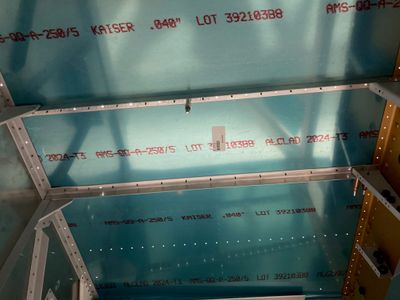
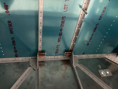
Nothing too fancy, I clamped the floor stiffeners to the structure, then drilled the two holes on both sides of the stiffener. After that, I drilled all the bottom holes through the bottom skin.
Also, I drilled two out of three holes in the cover support ribs. I couldn't drill the hole closest to the F-704 as it is too close to the bulkhead for my angle drill. I think I will be able to drill that hole if I remove the bottom skin.
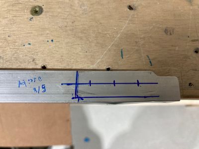
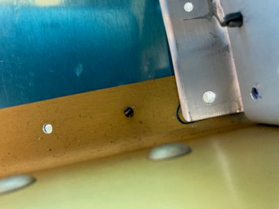
For some reason, I did not drill the holes in the firewall angles F-601-J, so I need to locate and drill them now. To do that, I marked how much the stiffener overlaps with the angle and placed the holes. The plans call for an exact 1/4" distance from the edge of the firewall angle. However, I don't like drilling that close to the edge, especially, in a thick material where small tilting of the drill can move the hole. Based on my markings, I have a 5/8" total overlap, so I placed the holes at 5/16" (I also moved the aftmost hole forward by 1/16", to get the same 5/16" edge distance).
Then I drilled the holes in the angles and checked that edge distances look good.
Finally, drilled the holes with my angle drill. First, to #40, then upsized to #30. I actually like how the drill works in thick materials -- it pulls itself into the existing hole. I think it self-aligns much better than reamers do.
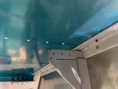
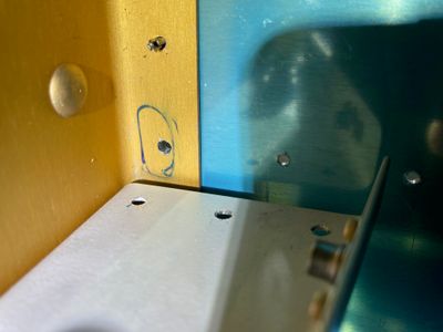
Update: well, after I thought I was done, I looked at the holes and realized that the front part of the F-704 bulkhead was not clecoed to the skin and was not in the correct position. So the holes in the F-704 came out quite elongated.
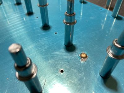
After filing the skin with the round file (to "elongate" them the same way as the hole in the F-704 was elongated) I reamed the holes to #30.
This is what it looks like from the inside.
The edge distance on the stiffeners came out to be ~0.230" and ~0.240", which is more than the minimum as per the MIL Spec, 0.219".
The hole looks clean.
Now the question, is what to do next?
One option is to put AN426AD4 rivets. However, their head is bigger, and there might be not enough material in the F-704 flange and the F-776 center bottom skin for the countersink.
Another option is to use NAS1097AD4 rivets. Since their head is the same size as a regular AN426AD3, they should require the same countersink size.
The third option would be to dimple everything and hope that I can fit the floor stiffeners. However, this is exactly what plans say not to do. Not sure exactly why. However, even in that case, the aluminum angle is pretty thin and won't have too much material for the "substructure" countersink (flush plus 0.007").
The fourth option would be to put a universal rivet, AN470AD4 there. Like this:
Finally, the fifth option is to countersink the forward bottom skin. Based on my calculations, the depth of a countersink for an AN426AD4 rivet is ~0.039, and the forward bottom skin thickness is 0.040".
P.S. The Van's support thinks that countersinking for AN426AD4 rivet (as per the plans) should not be an issue as it only a single hole. Also, edge distance on the floor stiffener is not an issue too.
