Riveting the stiffeners and assembling the skeleton 5h
5h
June 3, 2022
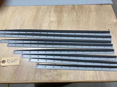
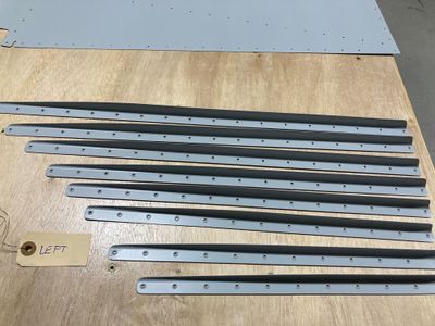
The next day, after the primer has dried, dimpling time.
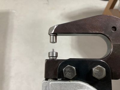
I dimpled all the stiffeners using a narrow female dimple die (to avoid damaging the flange with the standard dimple die, which is wider).
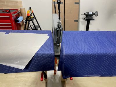
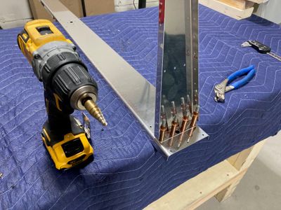
Then I constructed a contraption to mount DRDT-2 between the two tables (I clamped two pieces of 2x4 between the table legs). I don't want to construct a table around DRDT-2 since I don't have much space to store it, and for the rudder skins, this contraption worked just fine. I will see if I need to improve it for the bigger skins. One issue I have with it is that I cannot push DRDT-2 far back because it will not be supported by 2x4 "joists". Maybe, I'll make a narrow piece of plywood to put on these "joists" so I can position DRDT-2 differently.
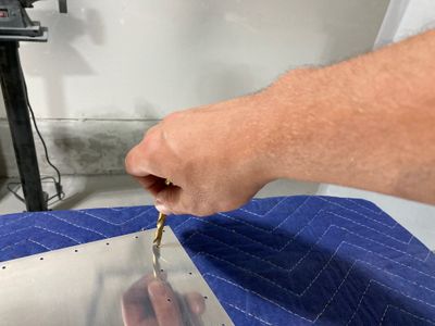
Initially, I did not want to deburr holes in the skins because they are so thin. Since I used a reamer to open the holes, I thought I would not get a lot of burrs. On the primed side, I removed all burrs when I scuffed the skins during the etching process. However, later I used a drill bit (rotate it between fingers) to remove small burrs from the exterior side of the skins.
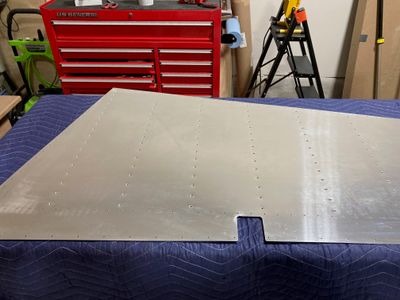
Dimpled the right side skin.
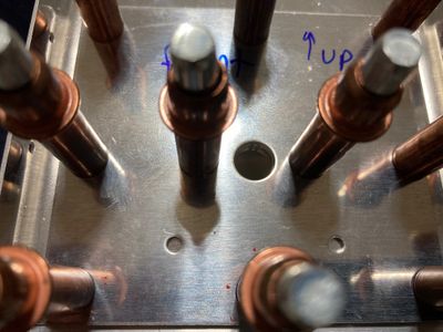
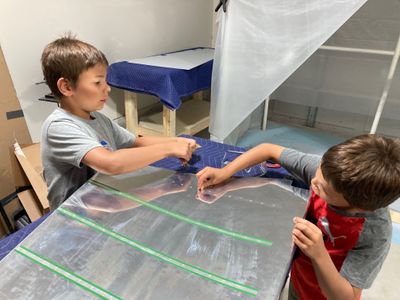
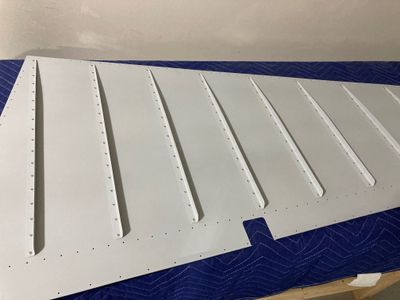
Then, with the help of my apprentices, I back riveted stiffeners to the skins.
I over-driven a few trailing edge rivets, mostly because the manual was mentioning that you need to fully set them so they don't interfere with the other side. I haven't decided yet if I want to re-install them or leave them the way they are. Will take a look at them again tomorrow.
After that, it was too late to make noise riveting, so I switched to the next section, building the rudder skeleton.
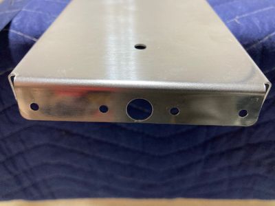
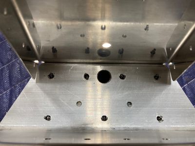
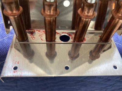
The first step was to upsize the hole in the bottom rib flange for the bolt. Looks awkward, but it is as per the plans.
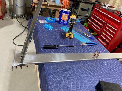
Then I match-drilled the holes in the bottom part of the rudder skeleton. I opted to do it in a different order than suggested in the manual. The manual wants you to bolt the horn to the spar, then match-drill the holes. However, since both the spar and the horn were pre-drilled already and the holes all matched, I simply clecoed everything and match-drilled with the reamer.
While reaming, I found two holes on both the reinforcing plate and the rudder horn which matched each other, but there was no mention of them in the manual. The theory on the VAF board was that they are used in RV-14 as these two parts are shared. I checked RV-14 plans, and indeed these two holes are used there. I asked Van's what to do with them (but it looks like you can both ignore them as per plans or drill them to install two extra rivets -- there is enough spacing there).
And it was the end of the session for that day!
