Countersinking the rudder wedge and priming 3h
3h
June 7, 2022
Today I countersinked the AEX wedge and primed the parts.
The first step was to countersink the AEX wedge. I had a Cleaveland jig for countersinking the wedge which I intended to use. I used it for my second practice kit and, as far as I remember, it turned out okay (but not perfect).
For the comparison, the first practice kit I countersinked by hand, and the result was terrible.
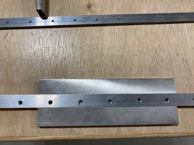
Here you can see the rudder wedge (on the top) and the first practice kit wedge (on the bottom). A lot of holes were oversized and/or trilobed. Also note how holes are not centered: I did not have a good jig for drilling at 84º degrees and in the practice kit, you only have holes on one of the skins. Therefore, the holes were in slightly different positions.
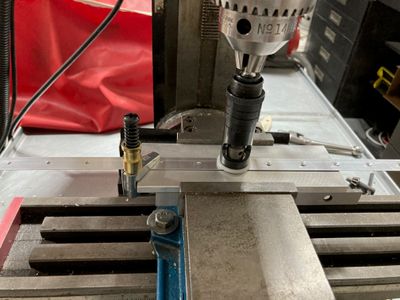
Since the rudder wedge was predrilled already, I thought that I can have a more repeatable setup. The idea was to only allow one dimension of freedom (along with the wedge) and fix the distance from the edge to the hole.
With distance from the edge fixed, it would allow me to drill a small #40 hole in the jig itself and use that hole for centering the countersink pilot. If I lock the jig such that this pilot hole is centered relative to the spindle, all I need to do is to move the wedge from hole to hole.
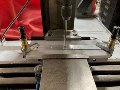
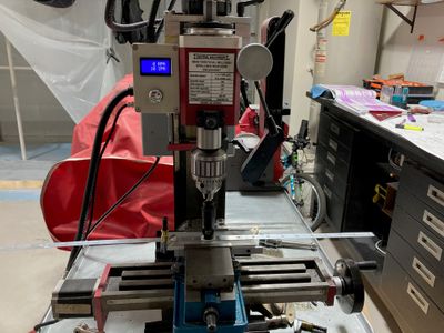
For that, I locked the Cleaveland jig in my milling machine vise, clamped the wedge to it, and used my wiggler tool to center the spindle over the wedge hole.
Then I drilled the pilot hole. I actually used #41, which was enough for the pilot to fit. With that setup the process was the following:
- Center the wedge on the spindle (use countersink pilot for centering).
- Lock the wedge with the cleco clamp.
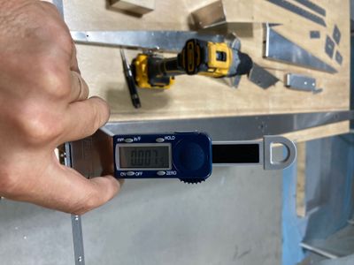
- Countersink. I configured the countersink cage to do the 7 thou past flush, which is a general recommendation from Section 5 of the manual. I used that setting on practice kit #2 and got pretty good results with it.
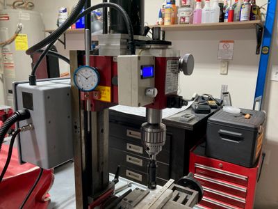
For the depth control, initially, I thought to use the countersink cage only. I have an indicator stop on the mill, but I thought that the setup is not repeatable enough for it to work (I expected some minor, few thou, differences between the holes). However, it turned out that setup was repeatable enough and it would always stop at the same indicator position. So I used the indicator to verify the depth set by the cage.
This is my custom-made indicator stop for the mill.
With this setup, I got about ~7 thou past the flush, as per the depth gauge. Well, to be honest, it is hard to measure this depth with good repeatability (since even a small movement of the rivet shows different results). It was deep enough that a dimple would fit in it, but would not wobble. The ultimate test would be to fit it once the whole rudder is riveted and see how well it fits.
This is what the process looked like. I had a concern that due to the small differences in hole locations, it won't always center in the hole, but it turned out to be okay.
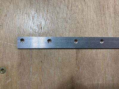
Finally, the whole wedge is countersinked. The last hole is the one I (and others as well) had issues with on my practice kits, but with this setup, it turned out to be fine.
After that, I cleaned everything and primed the parts.
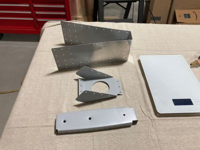
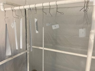
Here are some of the primed parts.
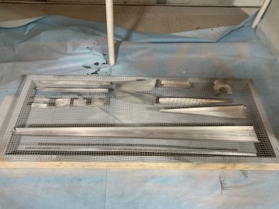
I don't use hooks for the priming as they turned out to be inconvenient. Since my paint booth is very small, I need to move parts around to be able to shoot them from all directions, so the frame with the chicken net works better (I probably should make a table from it).
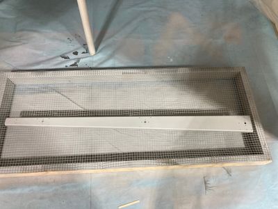
Also, I primed the exterior part of the counterbalance skin that would go under the rudder skins. I primed a bit more than necessary, I assume that this extra primer will be scuffed when the whole plane will be prepared for the painting. Or maybe I will remove that primer myself.
