Fitting the rudder pedals block 2h
2h
March 8, 2023
Today I fitted the rudder pedal block to the stiffeners.
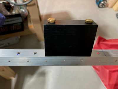
The overall idea was to locate the holes on my mill from specific reference surfaces to avoid match-drilling in the fuselage, all under the assumption that I got the bearing angles correct such that the pedals move freely when blocks are completely flat to both skins.
For the blocks themselves, I used the following reference surfaces:
- The side that goes flat to the skin. The holes are 3/8" from that surface.
- The forward edge of the block. The first hole is 3/8" from that surface and the second hole is 2-3/8" from it. This accounts for the small differences in the length of the blocks (although it probably doesn't matter that much, the difference between the blocks is probably less than 0.010").
- The face that goes to the angle. The holes are drilled from that surface. In the case drill wanders a bit, these holes will be located precisely (while the exit holes might be a bit off).
Initially, I placed the edge of the bearing blocks at 3-5/8", which is the original 3" as per plans, plus half the difference of the bearing block length (2-3/4" versus 4"). However, given that these pedals have the brakes on the back, and there was some interference with the firewall angles, I moved them aft by 3/8", getting a 4" distance from the firewall to the edge of the bearing blocks.
I saw that other builders got the center block from Control Approach, but I thought I did not. I did not bother to ask for it because I wanted to make my blocks anyway (to get the "standard" spacing of the holes). While looking at the pedals, I found a surprise behind one of them!
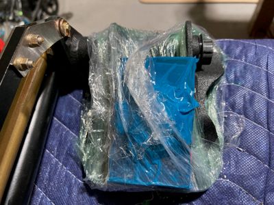
Turned out, the center block (and the four bolts plus the safety wire) were taped to the back of the pedal. Oops.
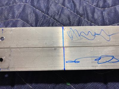
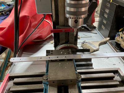
I took the stiffeners off the plane, located the lines with the wiggler tool on the mill, and drilled the 6 holes. The first hole is 3/8" from the line, then 1" spacing between them. The Y axis is positioned 3/8" from the back jaw of the vise.
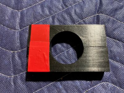
The blocks drop right in, in all the positions! Well, almost, it is a somewhat tight fit. I'll call it "precise".
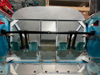
The pedals are installed in the second position. No issues when fitting -- the bolts fit right where they should!
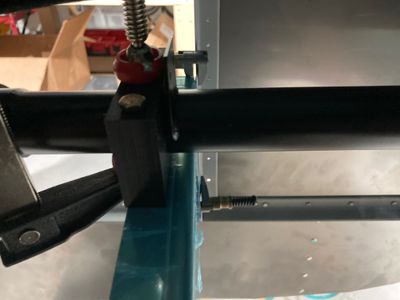
In parallel, I was trying to figure out how to fit the rudder pedal brace. Ideally, I need to position it exactly parallel to the holes on the sides, so I can drill the same 6 holes on it on a mill (or, at least, use a template to drill the 6 holes). I don't really want to match drill anything.
One issue I see is that if I place the rudder brace to the outboard of the firewall angle, I cannot position my central block due to welding on the pedals (I don't need this welding, it is presumably used on other models of RVs).
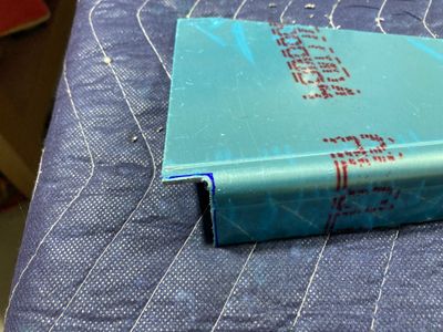
I think I can put the brace inboard, but then riveting it might be a problem. There is about a 1/8" gap between the firewall angle and the firewall recess. With the rudder brace being 1/16", it leaves me 1/16" for the rivet head.
The factory head of the universal rivet seems to be smaller than that, so that's one option. The other option would be to use a flush rivet. Or, I can squash the shop head to be less than 0.063". This is also possible, the minimum thickness for a -4 rivet is 0.050".
