Wiring tool
August 13, 2026
To manage all the wiring I'm doing, I created my own wiring tool!
I've already wired my wings, and one concern I had was whether I would preserve all the nitty-gritty details of the wiring. Wire gauges? What each label means? Connector pins? Or just the overall idea of what connects where?
At first, I started coding my decisions as JavaScript code: which wires I have, their sizes, the waypoints they go through. Later I switched to the KiCad tool to get actual diagrams of my wiring. However, KiCad is not really designed for designing aviation harnesses: even though it works, it is still very inconvenient to use.
My main concern was to lose some of the wiring decisions that I have implemented already. In KiCad, diagrams represent the connections. If you change your diagrams to improve readability or move components from one diagram to another, there is a risk you lose some connections or connect the wrong pin or something like that.
So I came up with the idea: to create a "digital twin" for my wires, a complete wiring model that is close to reality, and only use diagrams as a way to "look" at that model. The edits are still done via the diagrams, but destructive operations (such as disconnecting a wire) are done in a way that makes them hard to do accidentally.
Instead of deleting wires and re-doing them on another diagram, I used the idea of removing a device from a diagram. The wire connections are still in the model; you just don't see them on a diagram if you don't have either part of the connection on that diagram. To make diagrams "truthful", I added the concept of a "portal" -- a representation of a pin of a device that is not present on a diagram. For example, if a switch is connected to FlyLeds controller pin 9, and the FlyLeds controller is not on the diagram (but the switch is), there will be a netlist-like label for the FlyLeds controller pin 9 (which cannot be just "deleted" from the diagram).
This is the crux of the idea, with many more little details like the ability to hide some of the pins. For example, for Carling Contura V switches it is possible to hide their "illumination" pins -- if they are not relevant for a diagram. Or for Garmin-like devices, pretty much all of the pins could be hidden from a diagram. Hidden pins follow the rules of hidden devices -- so if there is a connection to a hidden pin, that connection will go to a "portal".
Therefore anything on a diagram is connected to some real-world object. If there is a ground symbol connected to a switch -- this ground symbol could be a portal for a forest of tab blocks, with a specific pin that this ground connects to! Or a Garmin backshell connector is an actual "pin" on a specific connector -- but hidden from the diagram. It shows as a disconnected triangle with an "S" in it, but in reality, it's just a "portal" for a virtual "backshell" pin on some specific connector.
In the same way, I didn't like the general idea of "shielded wires", so I added first-class support for cables instead. Each cable has a number of wires, and in addition, can have a special wire called "shield" -- which represents a shield.
The tool is still in a very early stage of development, and data entry is a bit rough in some areas, but it's probably already 80% of what I need.
Here are some screenshots of the diagrams. First, the panel switches:
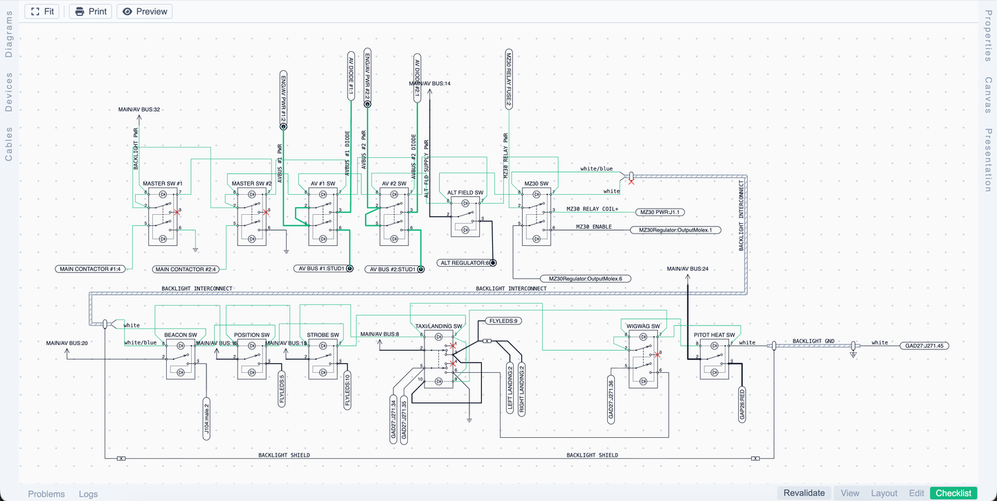
I don't think I succeeded in completely decluttering the diagrams, but I think it's pretty close to a diagram that would have been drawn just for visualization purposes.
And here is my power distribution model.
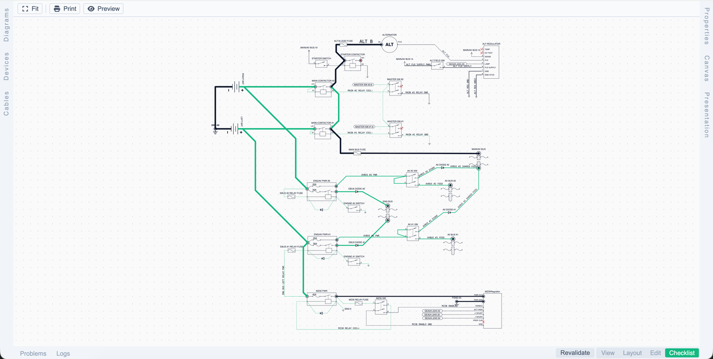
Both diagrams are in "checklist" mode where they highlight completed wires.
I put a demo version at https://harnessery.com/. The name is kind of ugly, but I couldn't think of something better that I could find a domain for. So it will do for now.
The demo is a snapshot of my project, with all the editing, but without the ability to save the project.
